Compact Directional Valves - Non-compensated and Post-compensated - Directional elements EDC Series

EDC-P1

Valve element with direct proportional flow sharing control.

It can achieve the simultaneous activation of different actuators by distributing the available flow proportionally to the speeds selected by the operator.

All simultaneous movements go on at the same reciprocal speed also in case of flow shortage.

Each energized actuator receives a pressure compensated flow.

  • No shuttle valve fitted.

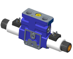
Wet pin proportional tubes for DC coils, with push rod for mechanical override; nickel plated surface.

Manual override (push-button, screw type or lever) available as option.

Different plug-in connectors available: see ordering details.

Size 6

Series 00

Maximum operating pressure 310 bar (4500 psi)

Maximum flow at 14 bar (203 psi) 59 l/min (15.59 gpm)

Maximum flow at 18 bar (261 psi) 65 l/min (17.17 gpm)

Ports connections planned G 3/8 - G 1/2 - SAE8 and Modular

NEW spool position sensor available for this valve. See RE18300-30

RE18301-15-order

Symbols

RE18301-15-sym

Spool variant and Flow pattern

RE18301-15-01
RE18301-15-02

The sandwich plate design directional valve elements L8581… are compact direct operated pressure compensated proportional solenoid valves which control the start, the stop, the direction and the quantity of the oil flow, with a FLOW SHARING principle. These elements basically consist of a stackable housing (1) with a control spool, two solenoids (4), two return springs. Energized by an electronic feed regulator, each solenoid (4) displaces the control spool from its neutral-central position “0” proportionally to the current received. When the spool is shifted and the metering notch is open, flow delivery starts and is controlled by a 3 way pressure compensator followed by a check valve for each port A and B. The compensator, balanced by the LS pressure at the opposite end, lifts up and unloads a regulated flow which is sent to the A (or B) port through the relevant check valve; at the same time the opposite port allows oil return to tank.

LS pressure reaches the compensator “dead end” directly from the A or B port, while the check valves lock eventual pressure oscillations which could affect the compensator function.

When the solenoid is de-energized, the return spring pushes the spool thrust washer back against the housing and the spool returns in its neutral-central position.

Each coil (4) is fastened to the solenoid tube by the ring nut (7). A pin allows to push the spool under emergency conditions, when the solenoid cannot be energized, like in case of voltage shortage.

Code
Voltage [V]
Connector type
Coil description
Marking
Coil Mat no.
=OB 01
12 DC
EN 175301-803 (Ex. DIN 43650)
GP45 01 - 45 K4
12 DC
R901022180
=OB 03
12 DC
AMP JUNIOR
GP45 03 - 45 C4
12 DC
R901022680
=OB 07
12 DC
DEUTSCH DT 04-2P
GP45 07 - 45 K40
12 DC
R901272648
=OC 01
24 DC
EN 175301-803 (Ex. DIN 43650)
GP45 01 - 45 K4
24 DC
R901022174
=OC 03
24 DC
AMP JUNIOR
GP45 03 - 45 C4
24 DC
R901022683
=OC 07
24 DC
DEUTSCH DT 04-2P
GP45 07 - 45 K40
24 DC
R901272647
General:
Valve element with 2 solenoids:
  • 3.95 kg (8.71 lbs)
Valve element with 1 solenoid:
  • 3.60 kg (7.91 lbs)
Fluid Temperature:
  • -30....+90 (-22....+194) (NBR seals)
MTTFd:
  • 150 years see RE 18350-51
Hydraulic:
Maximum pressure at P, A and B ports:
  • 310 bar (4500 psi)
Maximum pressure at T:
  • 210 (3050)
Maximum pressure with lever emergency at T:
  • 140 bar (2030 psi)
Max. regulated flow at 14 bar (203 psi):
  • 59 l/min (15.59 gpm)
Max. regulated flow at 18 bar (261 psi):
  • 65 l/min (17.17 gpm)
E-schemes flow pattern symmetrical closed pass in the neutral position (connection from A to T and B to T):
  • Approx. 2% of the nominal cross-section
Hydraulic fluidGeneral properties: it must have physical lubricating and chemical properties suitable for use in hydraulic systems such as, for example:
  • Mineral oil based hydraulic fluids HL (DIN 51524 part 1). For use of environmentally acceptable fluids (vegetable or polyglycol base) please consult us.
Fluid Temperature:
  • -30....+100°C (-22....+212°F) (NBR seals)
Permissible degree of fluid contamination:
  • ISO 4572: βₓ≥75 X=12...15 NAS 1638: class 9
Viscosity range:
  • 20....380 mm²/s (optimal 30....46)
Electrical:
Voltage type:
  • 120 Hz PWM
Voltage tolerance (nominal voltage):
  • -10 .... +10%
Duty:
  • Continuous, with ambient temperature ≤ 90°C (194°F)
Coil wire temperature not to be exceeded:
  • 180°C (356°F)
Insulation class:
  • H
Compliance with:
  • Low Voltage Directive LVD 73/23/EC (2006/95/EC), 2004/108/EC
Coil weight:
  • 0.335 kg (0.739 lbs)
Voltage:
  • 12 V
  • 24 V
Nominal 100% current:
  • 1.8 A
  • 1.2 A
Coil resistance (nominal at 20°C (68°F)):
  • Note: For applications with different specifications consult us
  • 3.3 Ω - Cold value
  • 7.2 Ω - Cold value

Characteristic curves Q=Q (I)

RE18301-15-03

Nominal flow Qnom=Qnom (ΔP ls)

RE18301-15-04

Pressure drop Δp = Δp(Q) (PIN- POUT) to the next section

RE18301-15-05

Pressure drop Δp = Δp(Q) with spool B2S9

RE18301-15-06

LS drain

RE18301-15-07

The curves refer to the spool fully open.

Measured with hydraulic fluid ISO-VG32 at 45° ±5 °C (113° ±9 °F); ambient temperature 20 °C (68 °F).

RE18301-15-dim1
1
Solenoid tube Ø 23 mm (0.91 inch).
2
Plug for 2 positions versions (4/2).
3
Ring nut for coil locking (Ø 30.3 mm).Torque 6 – 7 Nm (4.4 – 5.2 ft-lb).
4
Flange specifications for coupling to ED intermediate elements.
5
For tie rod and tightening torque information see data sheet RE 18301-90.
6
Clearance needed for connector removal.
7
A and B ports.
8
Identification label.
9
Optional push-button manual override, 0P type, for spool opening: it is pressure stuck to the ring nut for coil locking. Mat no. R933003424.
10
Optional screw type manual override, 0F type, for spool opening: it is screwed (torque 6-7 Nm (4.4-5.2 ft-lb)) to the tube as replacement of the coil ring nut. Mat no. R930056486.
11
Optional push-button manual override NP (black) and RP (red) type, for spool opening. It is screwed (torque 6-7Nm(4.4-5.2 ft-lb)) to the tube as replacement of the coil ring nut. Mat no. R930056488(black) - R930056489 (red).
12
Optional twist type manual override, 0T type, for spool opening and locking in the energised position. It is screwed (torque 6-7Nm (44-5.2 ft-lb)) to the tube as replacement of the coil ring nut. Mat no. R930056487
13
Four threaded holes M5 deepth 12mm (0.47 inch) for fitting a secondary flangeable element. Bolts M5 with recommended strength class DIN8.8: torque 5-6 Nm (3.6-4.4 ft-lb) (only for version with modular secondary valves).

External dimensions and fittings

RE18301-15-dim2
1
Ordering Details: HA (if fitted to side A) or HB (if fitted to side B)
2
Ordering Details: VA (if fitted to side A) or VB (if fitted to side B)
3
Ordering Details: H1 (if fitted to side A) or H9 (if fitted to side B)
4
Ordering Details: V1 (if fitted to side A) or V9 (if fitted to side B)
5
Ordering Details: XA (if fitted to side A) or XB (if fitted to side B)
6
Ordering Details: X1 (if fitted to side A) or X9 (if fitted to side B)

External dimensions for spool with nominal flow 9 and Z

RE18301-15-dim3
1
Flow-boost system only for spool with nominal flow 9 and Z.It always mounted on "b" side of the valve.

External dimensions for spool with nominal flow 9 and Z

RE18301-15-dim4
1
Flow-boost system only for spool with nominal flow 9 and Z. It always mounted on the opposite side of the lever manual override.

External dimensions for spool with nominal flow 9 and Z

RE18301-15-dim5
1
Flow-boost system only for spool with nominal flow 9 and Z. It always mounted on the opposite side of the lever manual override.
RE18301-15-08