HydraForce Will Help You Keep the Load in the Bucket

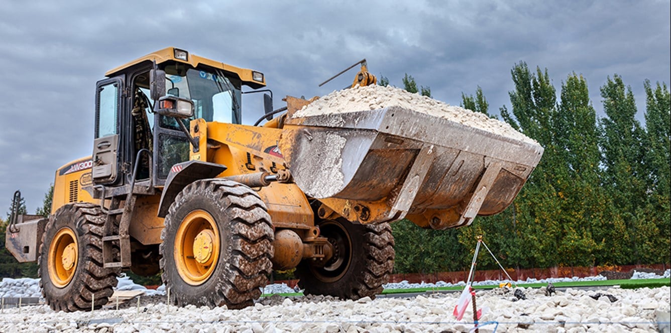
HydraForce hydraulic controls can enhance the capability of any wheel loader – from the compact 80 horsepower models, through the mid-range 80 to 200 HP models, up to the powerful 250 HP and above machines. HydraForce products for wheel loaders include flow sharing proportional valves, multi-function directional that enable efficient meter-in / meter-out flow sharing, and pilot valves for ancillary functions and directional control.


Request engineering assistance for more information about our space saving multi-function valves and flow sharing solutions.

Application Details

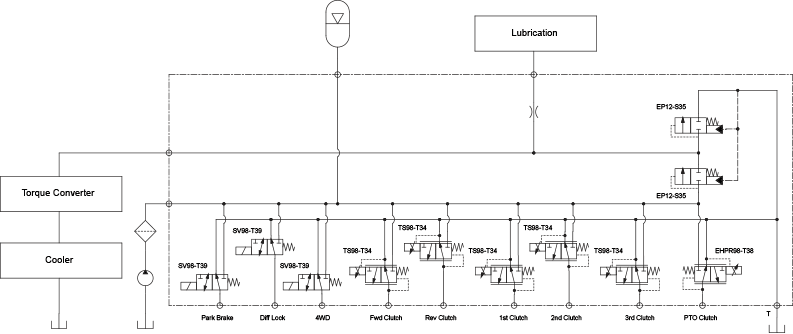
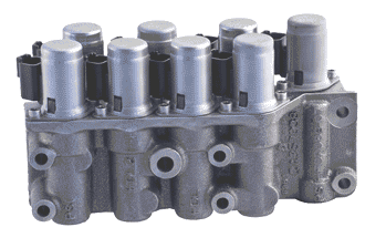
Transmission and PTO Solutions

• Clutch engage / disengage, Power Shift
• Accurate clutch pressure control
• Lubrication pressure control
• Main system pressure regulation
• Diff. Lock engage / disengage
• PTO control

The circuit shown has a nominal flow rate of 114 lpm/30 gpm with a main system relief valve.


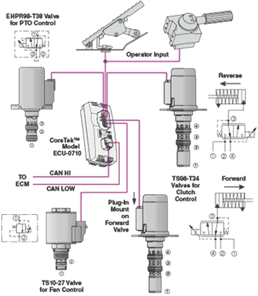
• Drop-In Valves Proportional Pressure Control Optimizes Clutch
  Engagement and Lube Oil Cooler Performance
• Modulating Valve Concept - For Soft and Modulated Engagement of
  Mechanical Operated Clutches


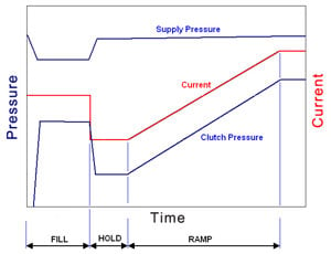
CLUTCH ENGAGEMENT PERFORMANCE (TS98-T34)

Optimize wheel loader powertrain systems with hydraulic
   cartridge valves and manifolds with programmable
   controllers.

Fan Drive Solutions


• Flow rates up to 190 lpm (50 gpm)
• Fail safe high or low
• Lubrication pressure control
• Preconfigured controls available
• Reduce horsepower consumption by up to 30%


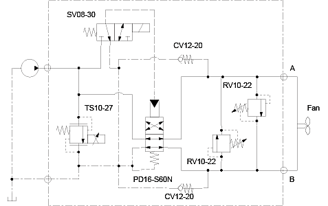
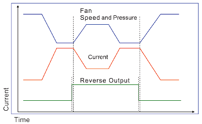
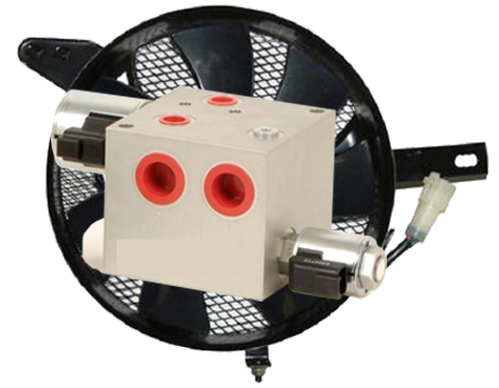
Control valves with multiple temperature inputs can be used to provide variable fan speed control depending on air temperature, load, and cooling requirements. If the radiator gets clogged, two-position, four-way solenoid valves can automatically reverse fan direction.

Electronic control of the hydraulic cooling system can be achieved using either an EFDR programmable valve driver or a CoreTek™ controller (ECU).

Boom Suspension Solutions


HydraForce suspension systems improve load-handling performance for wheel loaders and also enhance operator comfort by reducing vibration and improving ride control. Optimal combinations of cartridge valves in customized manifolds that feature an integral accumulator allow for smooth suspension of the boom.

– How Boom Suspension Works

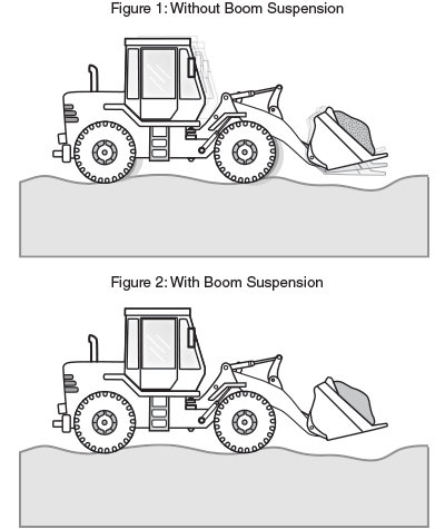
In a wheel loader, the boom suspension basically functions as a shock absorber for the bucket, creating a smoother ride for the operator.

Boom suspensions have the following benefits:
• Improved wheel contact with the ground, which helps steering and
  stopping
• Load “floats” over terrain, allowing higher transport speed, fewer
  repairs and downtime and increased productivity.
• Reduced vibration with loaded or unloaded bucket, fulfilling Vibration
  Directive 2002.44.EC and improving driver comfort.


Basic Boom Suspension Example:

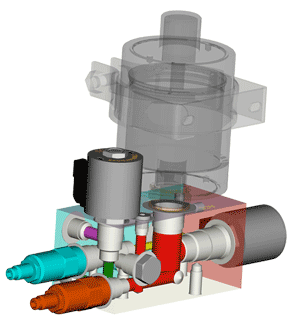
This manifold consists of solenoid valves SV12-28, SV10-22, pilot-operated relief valve with a reverse flow check and RV58-20A, a sequence valve with external pilot and drain with integral sensing PS10-41A and a check valve CV08-20.
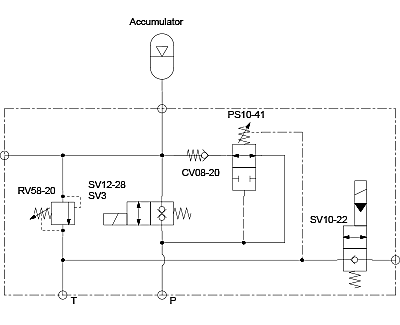
Ride control solutions fall into two categories: Passive or Active.


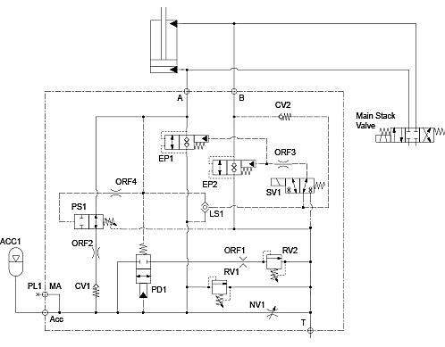
PASSIVE BOOM SUSPENSION —
In a passive system, everything is pre-set – accumulator volume, pre-charge pressure and damping characteristics. Height control and spring rate are set according to load. The suspension can then be switched on or off. When on, damping is preset to a “best fit” constant. This solution features a dedicated PED rated relief valve for accumulator protection and low pressure drop/ high flow HyPerformance™ logic elements for low damping pressure, and easy on/off pressure adjustment.

PASSIVE BOOM SUSPENSION
 

ACTIVE BOOM SUSPENSION —
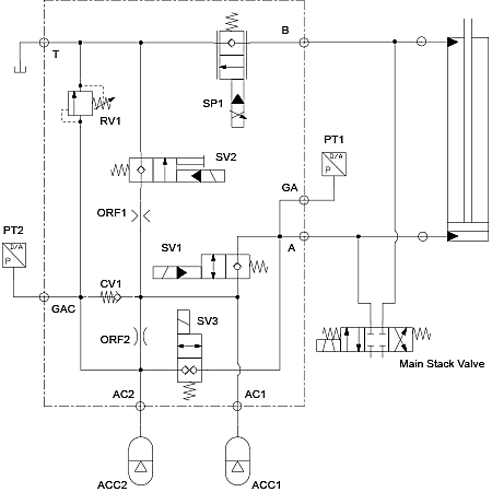
In an active system, at least one parameter is variable and can be changed depending on conditions.

Damping and spring rate can be adjusted in real time with a more sophisticated adaptive or active suspension system, which continuously adapts to the conditions of terrain, speed, etc. Fast, precise, repeatable valve response with low hysteresis is essential. HydraForce can provide fully customizable programming algorithms and hydraulic controls for a broad range of boom suspension solutions.
Primary Functions


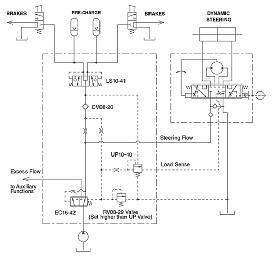
Primary Steering and Brake Solution.

• Dynamic Accumulator Charging Circuits used in conjunction with steering and braking units
— Primary Flow to the brake section of the circuit
— Auxiliary Flow diverted to the directional function


Directional Bridge

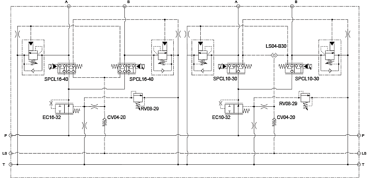
Load-holding bridge circuits provide the advantage of independent meter-in and meter-out timing with integral load sensing and pilot signaling, with minimal leakage. Circuit complexity, size and cost are minimized by using multi-function cartridge valves.

Use a bridge circuit to give priority control for lift and lower functions on wheel loaders.

Directional Bridge Circuit for Compact Wheel Loader

 
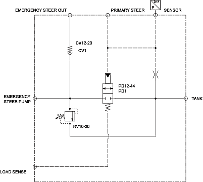
Emergency Steering


Emergency steering is used to enable steering in the event the engine dies or the brakes fail. The circuit below shows one-way hydraulic cartridge valves can be used in a load-sensing emergency steering circuit.

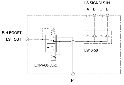
Load Sense Boost

Higher flows and shorter response times are possible with load sense boosting. When lower flows are adequate for the job, reduce standby pressures to save power.

Load Sense Boost Circuit

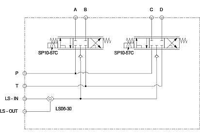
Tool Carrier Attachment

Hydraulic quick couplers allow wheel loaders the option to change attachments or tools. This Tool Carrier Attachment circuit has built-in load-sensing.

Tool Carrier and Attachment Circuit


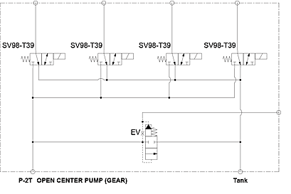
Pilot Selector

Customize the speed of actuation with a Pilot Selector Circuit. Pilot valves can be used to control the pressure and flow of hydraulic fluid to a series of directional valves. In the circuit below, a vented spool-type logic element (EV) controls the pressure provided by an open center gear pump to a series of four solenoid valves (SV).


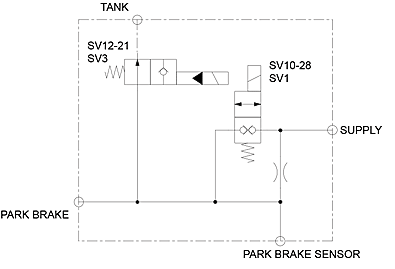
Loader Park Brake Circuit

Double blocking SV10-28 provides low leakage load holding to ensure park brake stays enabled.

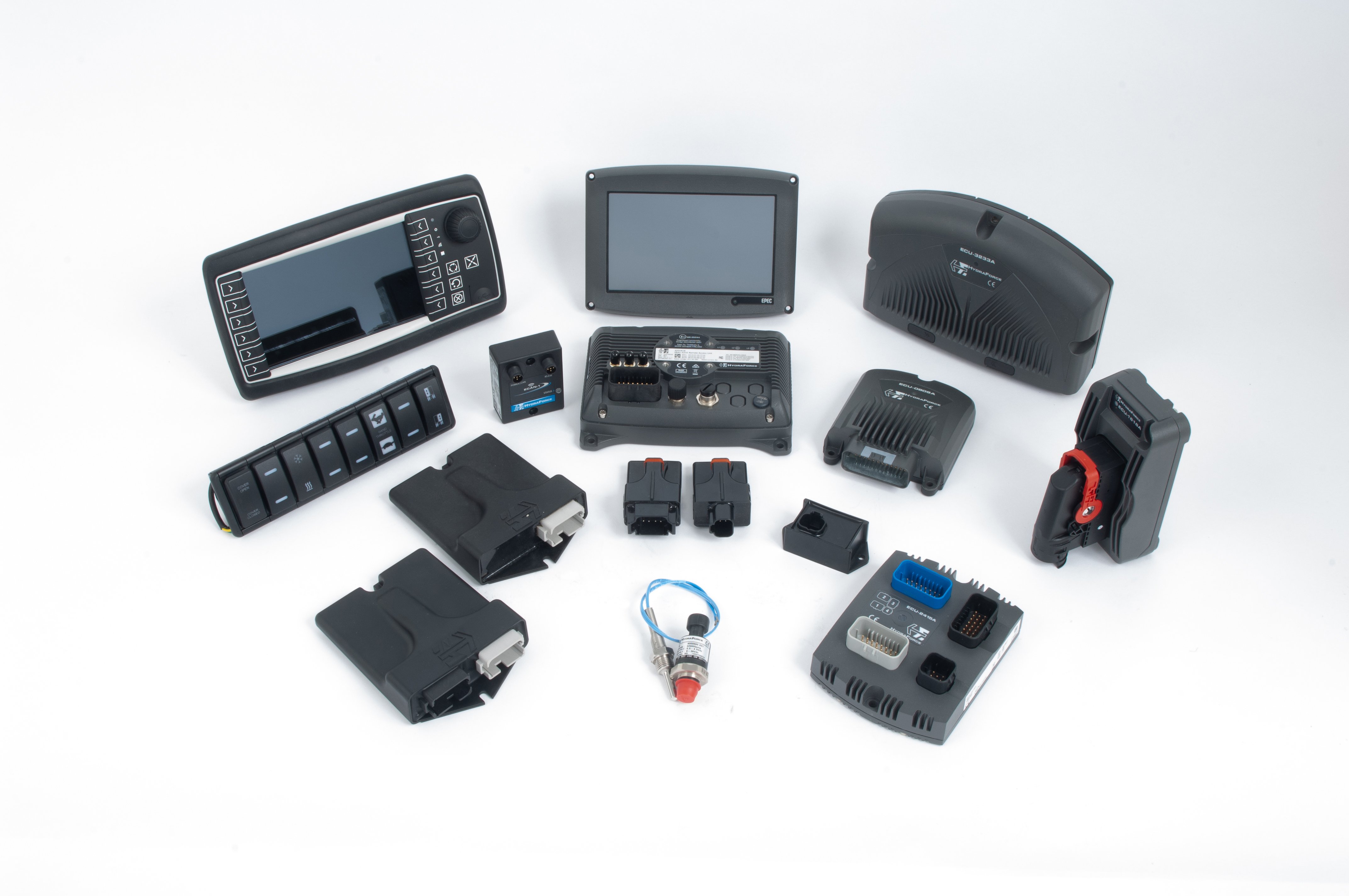
HydraForce is pleased to offer a full line of electronic vehicle control products integrating engine, transmission and other machine functions into a common J1939 or CAN Open Data Link control circuit.

These systems consist of rugged, field-proven components suitable for heavy-duty operating conditions. PWM digital signal logic maximizes efficiency, response and signal integrity under harsh environmental conditions. Reliability has been proven through extensive testing, as well as years of real-world application experience.

This is a complete line of the most rugged, heavy duty vehicle machine controllers, monitors, displays and electrical connectors for motion control and integrated machine control applications in mobile, off-highway and material handling equipment.

  • Reliable operation in the most demanding mobile equipment applications
  • Operating temperatures from -40 to 85°C
  • Chemical splash immunity
  • Moisture resistance to IP67 specifications
  • Fully resistant to EMI/RFI
  • Vibration resistant to 8 Grms (random) 24–200 Hz, 3-axis


Associated Applications

Telehandlers

Telehandlers

Gravity lowering | Main control | Variable speed fan drives | Steering and brake controls | Powertrain | Load moment limitation Learn More
Wheeled Excavators

Wheeled Excavators

Powertrain | Variable Speed Fan Drives | Suspension Systems | Main Controls | Auxiliary Functions | Electronic Controls Learn More
Skid Steer Loaders

Skid Steer Loaders

Powertrain | Variable Speed Fan Drives | Boom Suspension | Main Controls | Auxiliary Functions | Electronic Controls Learn More

VIDEO: Build a Better BOOM

Build a better boom with the HydraForce EBLV Boom Lock Valve. This innovative new hydraulic control solution provides safe lowering and protection from hose bursts for excavators, backhoes and other equipment.

Learn more about the HydraForce EBLV Boom Lock Valve
VIDEO: Build a Better BOOM

IOT Fleet Management for Wheel Loaders

Implemented on wheel loaders, HydraForce Internet of Things (IOT) technology improves reliability and availability and can even extend its lifetime. This is achieved by capturing and reporting operating data such as engine, powertrains, variable speed fan drives, suspension cab and boom suspension systems, auxiliary functions, and main and aux. functions and electronic controls, as well as through enhanced control and improved asset utilization.


The construction industry makes substantial investments in equipment and machinery. IOT fleet management technology from HydraForce raises ROI by improving availability and reducing maintenance costs.


IOT Fleet Management Solutions  

  • Monitoring and logging of key operating characteristics (cycles, hours, temperatures, pressures, vibration, etc.)
  • Reporting of key performance indicators
  • Remote adjustment of on-board settings (maximum permitted speeds, loads, etc.)
  • Updating of onboard software
  • Geo-location
  • Reducing the risk of breakdown and preventing unnecessary maintenance